Robot dynamics modelling
1. Definition of advanced identification methodologies for dynamic parameters
2. Robot modelling for dynamic parameter identification
3. Computation of the dynamic model of flexible parallel robots
1. Definition of advanced identification methodologies for dynamic parameters
1.1. Global identification of joint drive gains and dynamic parameters of robots
1.2. Identification of industial robot dynamic parameters based on their power model
1.1. Global identification of joint drive gains and dynamic parameters of robots
Several schemes have been proposed in the literature to identify the dynamic parameters of robots. Most of the dynamic off-line identification methods:
- use an Inverse Dynamic Identification Model (IDIM) that gives the linear relations between the joint forces/torques and the dynamic parameters,
- build an over-determined linear system of equations obtained by sampling the IDIM while the robot is tracking some trajectories in position closed-loop control,
- estimate the parameter values using least squares techniques (LS). This procedure is called the IDIM-LS technique.
Good experimental results can be obtained if:
- a well-tuned derivative band-pass filtering of joint position is used to calculate the joint velocities and accelerations,
- accurate values for joint drive gains are known to calculate the joint force/torque as the product of the input references of the motor current loop by the joint drive gains
This requires the calibration of the drive train constituted by a current controlled voltage source amplifier with gain Gt which supplies a permanent magnet DC or a brushless motor with torque constant Kt coupled to the link through direct drive or gear train with gear ratio N. Because of large values of the gear ratio for industrial robots, (N>50), the total joint drive gain, gd=N Gt Kt, is very sensitive to errors in Gt and Kt which must be accurately measured from special, time consuming, heavy tests on amplifiers and motors, which require opening the drive chain of each joint. This sensitivity to errors directly affects the accuracy of the force/torque computation as well as the interaction force between the robot and its environment or payload estimations that are required in many modern robotic applications.
We have introduced a new method for the global identification of all robot dynamic parameters, including joint drive gains, using the input reference of the motor current loop and the joint position sampled data while the robot is tracking:
- one reference trajectory without load fixed on the robot and,
- one trajectory with a known payload fixed on the robot.
Inertial payload parameters are measured or calculated with a CAD software. Contrary to the previous works, all dynamic parameters and drive gains are calculated in one step as the Total LS solution (TLS) of an over-determined system that takes into account the coupling between the robot axes. Such a method avoids the cumulative errors of the previous sequential procedures.
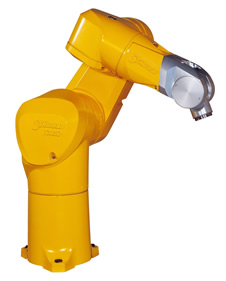
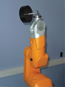
The method efficiency has been experimentally validated on an industrial robot manufactured by Stäubli: the TX-40 (Fig 1a) with the help of a calibrated payload (Fig. 1b) and on the Orthoglide robot developped at IRCCyN (Fig. 2).
 |
 |
(a) |
(b) |
Fig. 1. (a) The Stäubli TX-40 robot and (b) the TX-40 with the calibrated payload used for the global identification of joint drive gains and dynamic parameters of robots
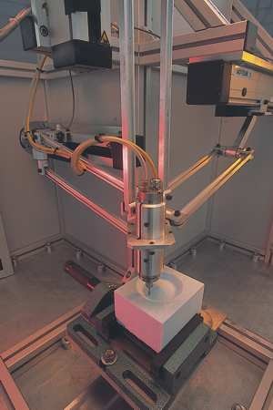
Fig. 2. The Orthoglide developped at IRCCyN.
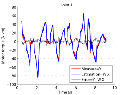
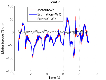
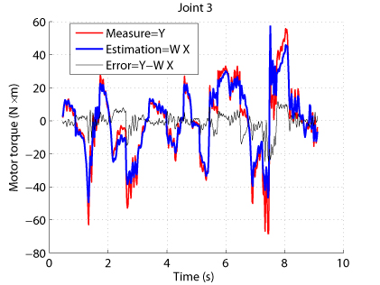
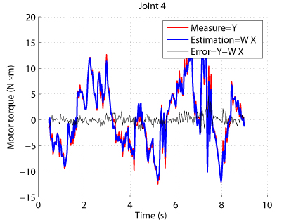
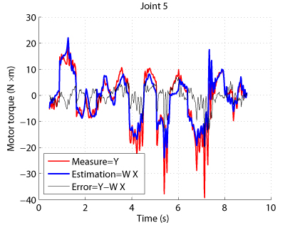
Results have shown that the estimation of the drive gains can be improved and leads to:
- better torque reconstruction (Fig. 3)
- lower tracking errors when computed torque control is used
- better payload and external effort estimation
 |
 |
 |
 |
 |
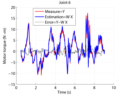 |
Fig. 3. Comparison between measured and estimaed input torques for the TX-40
More information about the method can be found in:
S. Briot and M. Gautier, "Global Identification of Joint Drive Gains and Dynamic Parameters of Parallel Robots," Multibody System Dynamics, 2015, Vol. 33, No. 1
M. Gautier and S. Briot, "Global Identification of Joint Drive Gains and Dynamic Parameters of Robots," ASME Journal of Dynamic Systems, Measurement and Control, 2014, Vol. 136, No. 5
M. Gautier and S. Briot, "Global Identification of Drive Gains Parameters of Robots Using a Known Payload ," Proceedings of the 2012 International Conference on Robotics and Automation (ICRA 2012), May 14-18, 2012, Saint Paul, MI, USA.
1.2. Identification of industial robot dynamic parameters based on their power model
To carry out the identification of the dynamic parameters, the Inverse Dynamic Identification Model (IDIM) is usually used. However, the computation of its symbolic expressions is extremely tedious. In order to simplify the procedure, the use of the Power Identification Model (PIM), which is dramatically simpler to obtain and that contains exactly the same dynamic parameters as the IDIM, was previously proposed. The PIM was used for the identification of the dynamic parameters of 2 degrees-of-freedom (DOF) planar serial robot but its application to a 6-DOF serial industrial robot was not successful and the results never published.
The reasons of this failure have been investiagted. We have shown that the PIM is much more sensitive to the choice of the exciting trajectories than the IDIM.
This is due to the intrinsic nature of serial industrial robots, for which the inertial parameters of the last joints (especially, those of the wrist) are the most difficult to identify. Indeed, the wrist elements are lighter and if their corresponding inertial parameters are melt in the same equation with those of the first joints, they will be poorly identified.
This problem is partially solved when using the IDIM procedure thanks to the block-triangular structure of the observation matrix. This block-triangular structure allows the minimization of the norm of error between the measures and the identification for each joint equations. This not the case when using the PIM for which the observation matrix is not block-triangular.
This problem can be avoided by creating a block-triangular regressor thanks to the use of optimal experimental trajectories. Using the property of matrices dh mentioned in section III for a n-DOF industrial serial robot, the block-triangular form of W can be obtained by carrying out at least n different types of trajectories that cancels some terms of W:
1. Trajectories with all joints moving altogether
2. Trajectories with joint 1 fixed, all the other joints (from 2 to n) moving altogether
3. Trajectories with joints 1 and 2 fixed, all the other joints (from 3 to n) moving altogether
…
n. Trajectories with joints 1 to n–1 fixed, joint n moving only.
Using these trajectories, the observation matrix built with the PIM takes block-triangular form and allows for the correct estimation of the dynamic parameters.
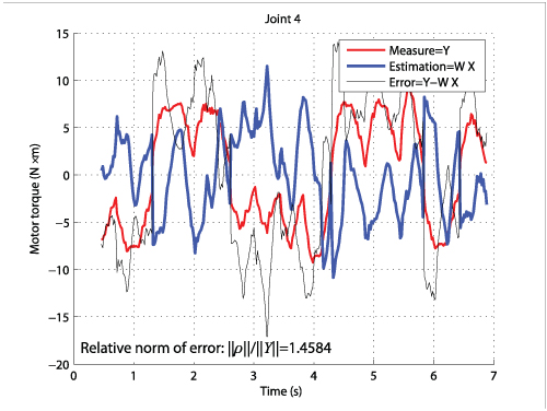
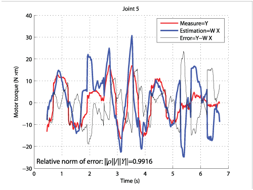
Experimental results on the TX-40 (Fig. 1a) have shown that:
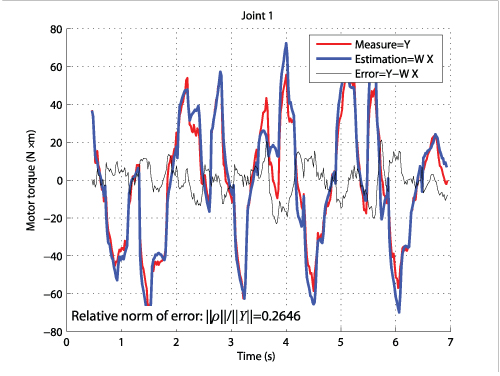
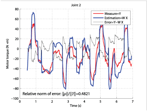
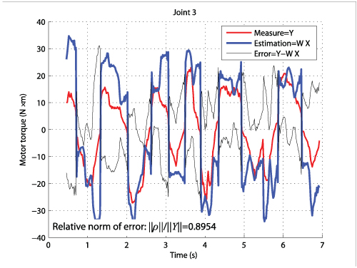
- without using the proposed methodology, it was not possible to identify the dynamic parameters (Fig. 4)
- with the proposed methodology, all dynamic parameters can be accurately identified (Fig. 5)
 |
 |
 |
 |
 |
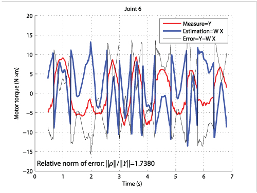 |
Fig. 4. Comparison between measured and estimaed input torques for the TX-40 (dynamic parameters estimated (with PIM) without using the adequate method)
|
|
|
|
|
|
Fig. 5. Comparison between measured and estimaed input torques for the TX-40 (dynamic parameters estimated (with PIM) by using the adequate method)
More information can be found in:
M. Gautier and S. Briot "Dynamic Parameter Identification of a 6 DOF Industrial Robot using Power Model," Proceedings of the 2013 IEEE International Conference on Robotics and Automation (ICRA 2013), May 6-10, 2013, Karlsruhe, Germany.
2. Robot modelling for dynamic parameter identification
2.1. Computation of the inverse dynamic identification model of parallel robots
2.1. Computation of the inverse dynamic identification model of parallel robots
Parallel robots have increasingly been used for a few decades. This is due to their main advantages compared to their serial counterparts that are: (i) a higher intrinsic rigidity, (ii) a larger payload-to-weight ratio and (iii) higher velocity and acceleration capacities. In order to obtain these interesting properties, a good controller should be implemented. Several approaches could be envisaged, but it appears that, for high-speed robots or when varying loads have to be compensated for (e.g. in pick-and-place operations or machining), computed torque control is generally used. This approach requires an accurate identification of the dynamic model of the robot with the load, which can be obtained if two main conditions are satisfied:
- A well-tuned derivative band-pass filtering of actuated joints position is used to calculate the actuated joints velocities and accelerations, and
- the values of actuator drive gains gt are accurately known to calculate the actuator force/torque as the product of the known control signal (computed by the numerical controller of the robot), i.e. the current references, by the drive gains.
However, it is often difficult or impossible to obtain robot manufacturers' data on joint drive gain values. And if available, data are usually given with an uncertainty greater than 10%, thus leading to identification and force calibration errors. Thus, drive gains must be calibrated. Some methods have been developed in the past to calibrate the drive train constituted by a current controlled voltage source amplifier with gain Gt which supplies a permanent magnet DC or a brushless motor with torque constant Kt coupled to the link directly or through gear train with gear ratio N. Each parameter was identified separately to then compute the drive gain gt=N Gt Kt, but these procedures were very sensitive to measurement errors and time consuming, requiring heavy tests on the drive chain. This sensitivity to errors directly affects the accuracy of the output force estimation.
We have proposed a new method for the global identification of all robot dynamic parameters, including joint drive gains (see Section on Advanced identification methodologies), using the input reference of the motor current loop and the joint position sampled data while the robot is tracking some reference trajectories without load fixed on the robot and some trajectories with a known payload fixed on the robot whose inertial parameters are measured or calculated with a CAD software. Contrary to the previous works, all dynamic parameters and drive gains are calculated altogether as the Total Least Square (TLS) solution of an over-determined system that takes into account the coupling between the robot axes.
This method was combined with the use of an Inverse Dynamic Identification Model (IDIM) that takes into account all the robot link dynamic parameters. Indeed, most of papers dealing with dynamic parameters identification for parallel robots propose a simplified dynamic model that takes into account the platform and drive chain dynamics only. Only few papers propose a systematic computation of the full IDIM. The most interesting and comprehensive works proposed in the past, methods for computing the IDIM based on Jourdain's principle or Lagrange multipliers were proposed. For all these works, the way to identify the drive gains is not treated and some Jacobian matrices, whose computation is not straightforward, are not clearly derived.
We have thus proposed a global methodology for filling those gaps. The aim of the approach is:
- to propose a systematic and straightforward procedure for the computation of the IDIM for parallel robots which is combined with a way to obtain a set of symmetric base parameters when robot legs are identical,
- to present a new method for the global identification of all robot dynamic parameters, including joint drive gains.
The approach is described in
S. Briot and M. Gautier, "Global Identification of Joint Drive Gains and Dynamic Parameters of Parallel Robots," Multibody System Dynamics.
in which all theoretical developments have been validated on the Orthoglide robot (Fig. 2).
Results have shown that the proposed method leads to:
- better torque reconstruction (Fig. 6)
- lower tracking errors when computed torque control is used
- better payload and external effort estimation
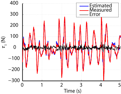
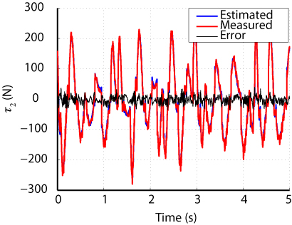
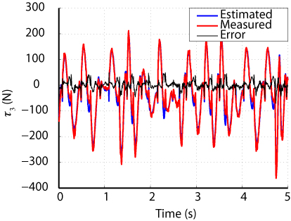
Fig. 6. Comparison between measured and estimaed input torques for the Orthoglide
More information in
S. Briot and M. Gautier, "Global Identification of Joint Drive Gains and Dynamic Parameters of Parallel Robots," Multibody System Dynamics, 2015, Vol. 33, No. 1.
2.2. Computation of the inverse dynamic identification model of parallel robots with actuation redundancy
For identifying the dynamic parameters of actuation redundant parallel robots (by comparison with parallel robots without actuation redundancy), a major problem arises. To better understand it, let us consider the simple example shown in Fig. 7. This mechanism with 1 DOF is moved though the use of two actuators mounted in parallel that can apply on the moving body of mass m two independent forces denoted as f1 and f2. For moving the mechanism, it exists infinity of possible forces to apply, e.g. [f1, f2]=m [xdd, 0], or also [f1, f2]=m [0, xdd] and even [f1, f2]=0.5 m [xdd, xdd] or many other force combinations (xdd is the mass acceleration). It should be mentioned here that the function c=|f1-f2| is called the overconstraint.
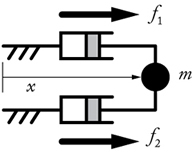
Fig. 7. A one DOF robot with actuation redundancy
Due to the existence of infinity of possible forces to apply, the usual IDIM that gives the linear relations between each force and the dynamic parameters cannot be computed because a unique formulation cannot be found. More generally, this problem appears for any kind of actuation redundant parallel robots: their inverse dynamic model is not unique and depends of the overconstraint in the mechanism.
It should be mentioned that the overconstraint could be fixed using a proper controller. However, as shown by our own experience in the field, most of the time, manufacturers of industrial robots do not want to give information about their own controller, or even, in worst cases, the controller does not fix the overcontraint. In such cases, the value of the overconstraint cannot be considered a priori known in the identification process as this quantity cannot be measured. Thus, identification using the usual IDIM for redundant parallel robots cannot be carried out.
To avoid the potential lack of information from the controller, another method should be proposed. Considering again the simple system presented in Fig. 7, it can be demonstrated that its dynamics can be uniquely described if the equations are projected no more on the actuators, as usual, but on the moving body such that: f1+f2=m xdd. Thus, by projecting the dynamic equations on a body different from the actuators, a modified IDIM formulation can be obtained. Contrary to the usual IDIM, this modified formulation does not express anymore the linear relations between each joint force and the dynamic parameters, but between \textit{a linear combination of the joint forces} and the dynamic parameters. It should be mentioned that this formulation can be used in any case, the value of the overconstraint c=|f1-f2| being known or not.
We have generalized the previously described approach to any kind of actuation redundant parallel robots and to propose a systematic and straightforward procedure for their dynamic parameter identification. This procedure is universal (i.e. it can be applied for any actuation redundant parallel robot for which the value of the overconstraint is known or not) and is based on the computation of a modified IDIM, linear with respect to the inertial parameters, that does not require the knowledge of the overconstraint. Two different ways for computing the IDIM have been proposed. These formulations are straightforward, can be used for any type of parallel robots with actuation redundancy and minimize the number of intermediate variables and operators used for the symbolic computation of the model. This point is important in identification as it minimizes the risk of error propagation (due to the measurement noise) in the computation of the observation matrix. To the best of our knowledge, this is the first time that methods for computing the IDIM of actuation redundant parallel robots are proposed.
That procedure has been experimentally validated on a planar 3-DOF parallel robot with actuation redundancy developped in the LIRMM, and named the DualV (Fig. 8).
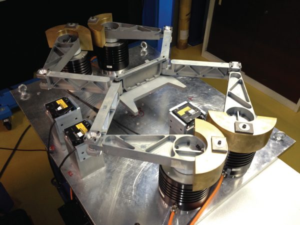
Fig. 8.The robot DualV developped at the LIRMM.
Results have shown that the proposed method leads to accurate parameter identification and good torque estimation (Fig. 9).
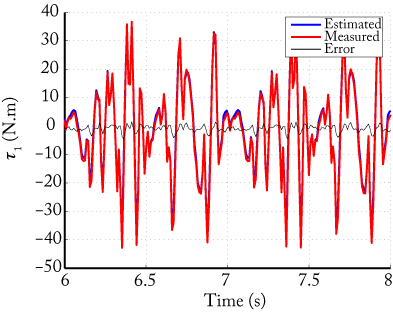
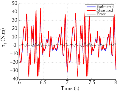
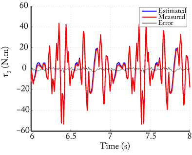
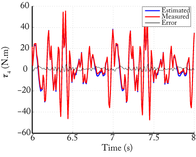
Fig. 9. Comparison between measured and estimaed input torques for the DualV
More information in
S. Briot, M. Gautier and S. Krut, "Dynamic Parameter Identification of Actuation Redundant Parallel Robots using their Power Identification Model: Application to the DualV," Proceedings of the IEEE/RSJ International Conference on Intelligent Robots and Systems (IROS 2013), November 3-7, 2013, Tokyo Big Sight, Japan
S. Briot, M. Gautier and S. Krut, "Dynamic Parameter Identification of Actuation Redundant Parallel Robots: Application to the DualV," Proceedings of the 2013 IEEE/ASME International Conference on Advanced Intelligent Mechatronics (AIM 2013), July 9-12, 2013, Wollongong, Australia
S. Briot, S. Krut and M. Gautier, "Dynamic Parameter Identification of Over-actuated Parallel Robots," ASME Journal of Dynamic Systems, Measurement and Control, 2015, Vol. 137, No. 11.
3. Computation of the dynamic model of flexible parallel robots
General methodologies for the computation of the elastodynamic models of parallel robots have been proposed in the past. However, the main drawback of such general methodologies is that they are not specifically designed for parallel robots and that they do not ensure the minimization of the number of operators for the symbolic computation of the model. To the best of our knowledge, a systematic procedure to compute the elastodynamic model (using distributed flexibilities) of parallel robot with a minimal numbers of operators has never been proposed, even if such models are useful for several different reasons:
-
In design optimization processes, optimization algorithms that test thousands of robot parameters are used. If the computational time required for the calculation of one iteration of the the elastodynamic model of the robot is not minimized, several days, and even month, can pass before the results are obtained.
-
Symbolic expressions, with a minimized number of variables and operators, are requested for computing the identification model, in order to decrease the risk of error propagation due to the noisy measured data.
We aimed at filling this gap. In order to minimize the number of operations, a generalized Newton-Euler (NE) model (which is known to reduce the number of operators) was used and combined with the principle of virtual powers (PVP). The Jacobian matrices defined in the PVP are computed using recursive algorithms that decrease the number of operators. For computing the full elastodynamic model of parallel robots,we used an approach which proposes to:
- convert the parallel robot into a virtual system defined by: (i) a tree-structure robot composed of the kinematic chains of the actual robot for which all joints (passive and active) are considered actuated and (ii) a free body (the platform which is considered as rigid) (Fig. 10),
- compute the elastodynamic model of this new virtual system,
- finally, close the loops by using the PVP.
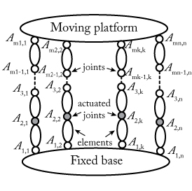
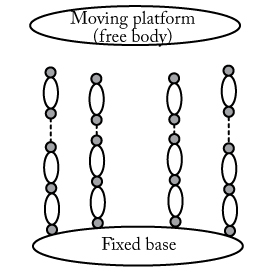
Fig. 10. A general parallel robot and the associated virtual system of the model computation
This method is effective, systematic and can be applied to any parallel robot.
Experimental validations made on a planar flexible parallel robot shown in Fig. 11 that the approach allows an accurate computation of the robot natural frequencies (less than 1% of error in the frequency range [12 - 100] Hz) and that the vibration prediction obtained in a short time of computation was good (Fig. 12).
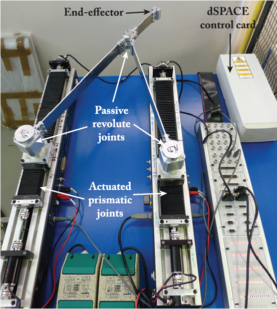
Fig. 11. Prototype of flexible parallel robot designed and manufactured at IRCCyN.
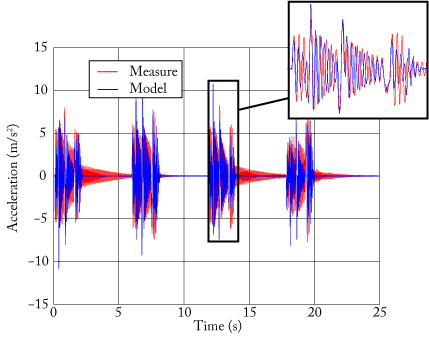
Fig. 12. Comparison between the acceleration of the end-effector measured by an accelerometer and the model prediction.
More information can be found in
S. Briot and W. Khalil, "Recursive and Symbolic Calculation of the Elastodynamic Model of Flexible Parallel Robots," The International Journal of Robotics Research, 2014, Vol. 33, No. 3, pp. 469-483.
C. Germain, S. Briot, S. Caro and P. Wenger, "Natural Frequency Computation of Parallel Robots," ASME Journal of Computational and Nonlinear Dynamics, 2015, Vol. 10, No. 2.